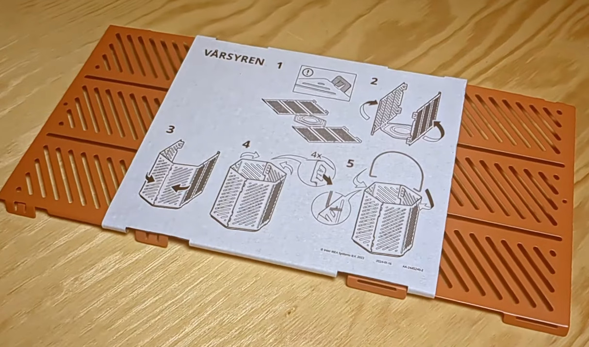
It’s fair to say that the average Hackaday reader enjoys putting together custom electronics. Some of those builds will be spaghetti on a breadboard, but at some point you’ll probably have a project that needs a permanent case. If you’re looking for a small case for your latest creation, check out [Julius Curt’s] modification of an IKEA Vårsyren lantern into a customizable enclosure!
Like most things IKEA, the Vårsyren lantern is flat pack — but rather than coming as a collection of wooden components, the lantern is made of sheet metal. It’s hexagonal in shape with a pair of three sided panels, so [Curt] simply snaps one of them off to make three sides of the final case. The other three sides are 3D printed with the STEP files provided so the case can be made to fit anything around 60x60x114 mm in size.
Cette communauté en constante expansion est devenue au fil du temps une référence en matière de CAO, regroupant aujourd’hui des ingénieurs et des concepteurs issus de plus de 1,3 million d’entreprises dans 195 pays, venus rechercher des modèles CAO de composants à intégrer dans leurs projets.
La société TraceParts, qui fournit l’une des principales plateformes de contenu CAO pour l’ingénierie et la conception industrielle, vient de franchir le seuil des six millions d’utilisateurs inscrits, un jalon qui reflète non seulement le succès de cette plateforme de CAO mais également l’importance croissante des modèles de CAO dans les processus de conception et d’approvisionnement des différents domaines de l’industrie. Cela d’autant que la tendance s’accélère, la barre des six millions d’utilisateurs inscrits étant atteinte moins de deux ans et demi après celle des cinq millions d’utilisateurs – c’était en avril 2023 – alors qu’il avait fallu trois et demi pour passer de quatre à cinq millions d’utilisateurs.
Cette communauté en constante expansion est ainsi devenue au fil du temps une référence en matière de CAO, regroupant aujourd’hui des ingénieurs et des concepteurs issus de plus de 1,3 million d’entreprises dans 195 pays, venus rechercher des modèles CAO de composants à intégrer dans leurs projets. La plateforme de TraceParts met à disposition plus de 2100 catalogues de produits en 3D et 108 millions de références produit et fournit un accès gratuit à des milliards de fichiers techniques, dont des dessins 2D, des modèles 3D, des fiches produits et des configurateurs, disponibles dans plus de 60 formats CAO. De quoi répondre aux besoins actuels de numérisation des procédés et opérations de conception, d’achat, de fabrication et de maintenance dans pratiquement tous les secteurs industriels.
Fondée en France et appartenant au groupe Trace fondé en 1990, la société TraceParts s’est développée avec des bureaux en Allemagne, aux États-Unis et en Chine, ainsi que des partenaires en Italie et en Turquie.
How hard can it be to create your own inductors? Get a wire. Coil it up. Right? Well, the devil is definitely in the details, and [Nick] wants to share his ten tips for building “the perfect” inductor. We don’t know about perfect, but we do think he brings up some very good points. Check out his video below.
If you are winding wire around your finger (or, as it appears in the video, a fork) or you are using a beefy ferrite core, you’ll find something interesting in the video.
Of course, the issue with inductors is that wires aren’t perfect, nor are core materials. Factors like this lead to inefficiency and loss, sometimes in a frequency-dependent way.
It looks like [Nick] is building a large switching power supply, so the subject inductor is a handful. He demonstrates some useful computational tools for analyzing data about cores, for example.
We learned a lot watching the tricks, but we were more interested in the inductor’s construction. We have to admit that the computed inductance of the coil matched quite closely to the measured value.
A few years ago, I bought an 8 mm home movie camera in a second hand store. I did a teardown on it here and pulled out for your pleasure those parts of it which I considered interesting. My vague plan was to put a Raspberry Pi in it, but instead it provided a gateway into the world of 8mm film technology. Since then I’ve recreated its Single 8 cartridge as a 3D printable model, produced a digital Super 8 cartridge, and had a movie camera with me at summer hacker camps.
When I tore down that Single 8 camera though, I don’t feel I did the subject justice. I concentrated on the lens, light metering, and viewfinder parts of the system, and didn’t bring you the shutter and film advance mechanism. That camera also lacked a couple of common 8 mm camera features; its light metering wasn’t through the lens, and its zoom lens was entirely manual. It’s time to dig out another 8 mm camera for a further teardown.
A Different Camera To Tear Down
The camera with a Super 8 cartridge inserted.
My test camera is a battered and scuffed Minolta XL-250 that I found in a second hand store for not a lot. It takes Super 8 cartridges, of which I have an expired Kodachrome example for the pictures, and it has the advantage of an extremely well-thought-out design that makes dismantling it very easy. So out it comes to be laid bare for Hackaday.
Once the sides have come off the camera, immediately you can see a set of very early-70s-analogue PCBs containing the light metering circuitry. Typically this would involve a CdS cell and a simple transistor circuit, and the aperture is controlled via a moving coil meter mechanism. This camera also has a large mostly-unpopulated PCB, giving a clue to some of the higher-end features found on its more expensive sibling.
The left hand side of the camera internals
The right hand side of the camera internals
Turning our attention inside the camera to the film gate, we can see the casting the film cartridge engages with, and the frame opening for the shutter To the left of that opening is a metal claw that engages with the sprocket holes in the film, thus providing the primary film advancement. The metal claw is attached to a slider on the back of the film gate, which in turn is operated by the rotation of the shutter, which is the next object of our attention.
The film gate is the silver component in the middle of the picture. The film advance claw is at its bottom left.
The back of the film gate assembly showing the film advance slider.
The shutter is a disc that spins at the frame rate, in this case 18 frames per second. It sits in the light path between the back of the lens system and the film gate. It has a segment cut out of the disc to let light through for part of the rotation, this is how it operates as a shutter. On its reverse is the cam which operates the slider for the film advancement claw, while its front is mirrored. This forms part of the through-the-lens light metering system which we’ll come to next.
The rear of the shutter (film side), showing the cam in the centre for the film advance.
The front of theshutter, showing the mirror for the light sensor.
The shutter in place. To its left attached to the PCB you can see the silver cylindrical light sensor.
The mirror on the front of the shutter is angled, which means that when the shutter is closed, the light is instead reflected upwards at right angles into a prism, which in turn directs the light to the light meter cell. The PCB on the other side must have a charge pump which takes this 18 Hz interrupted analogue signal and turns it into a DC to drive the moving coil mechanism. There’s a 10 uF capacitor which may be part of this circuit.
The W/T rocker operates this chain of levers.
The levers engage with the gearbox tucked under the lens.
Finally, we come to the powered zoom feature that was missing from the previous camera. On the top of the camera is a W/T rocker, for Wide/Telephoto. that operates the zoom. It is connected to a set of levers inside the case, which emerge as a pin at the front of the camera below the lens. This engages with a small gearbox that drives a knurled ring on the lens body, and selects forward and reverse to turn the ring. It’s driven by the same motor as the shutter, so it only works when the camera is operating.
I hope this look at my Minolta has filled in some of the gaps left by the previous article, and maybe revealed that there’s more than meets the eye when it comes to 8 mm movies. Careful though. If you dip a toe into this particular puddle it may suck you in head first!
He starts by demonstrating the vending process: a backlit vend button is pressed, an animation plays on the screen as a synthetic voice speaks through attached speakers, the vending mechanism rotates until a successful vend is detected with a photoelectric sensor (a photoresistor and an LED) or a timeout of 10 seconds is reached (the timeout is particularly important for cases when the stock of prizes is fully depleted).
For a successful vend the prize will roll out a vending tube and through some ramps, visible via a perspex side panel, into the receptacle, as the spooky voice announces the vend. It’s the photoelectric sensor which triggers the mask to speak.
The vending mechanism is a wheel that spins, the bouncy balls caught in a hole on the wheel, then fall through a vending tube. The cache of prizes are stored in a clear container attached to the top, which is secured with a keyed lock attached to the 3D printed lid. After unlocking the lid can be removed for restocking.
The whole device is built into an old PC case tower. The back panels have been replaced and sealed. The computer in the box is an ASUS CN60 Chromebox running Ubuntu Linux. The power button is obscured on the back of the case to avoid accidental pressing. The monitor is bolted on to the side panel with a perspex screen and connected to the Chromebox via VGA. Inside there are two power supplies, an Arduino Uno microcontroller, and an audio amplifier attached to a pair of speakers.
A 12V DC motor controls the vending prize wheel which feeds a prize into the vending tube. The vending tube has an LED on one side and a photoresistor on the other side that detects the vend. The software, running on Linux, is Python code using the Pygame library.
As we all look across a sea of lifeless, nearly identically-styled consumer goods, a few of us have become nostalgic for a time when products like stereo equipment, phones, appliances, homes, cars, and furniture didn’t all look indistinguishable. Computers suffered a similar fate, with nearly everything designed to be flat and minimalist with very little character. To be sure there are plenty of retro computing projects to recapture nostalgia, but to get useful, modern hardware in a fun, retro-themed case check out this desktop build from [Mar] that hides a few unique extras.
The PC itself is a modern build with an up-to-date operating system, but hidden in a 386-era case with early-90s styling. The real gem of this build though is the floppy disk drive, which looks unaltered on the surface. But its core functionality has been removed and in its place an Arduino sits, looking for NFC devices. The floppy disks similarly had NFC tags installed so that when they interact with the Arduino,it can send a command to the computer to launch a corresponding game. To the user it looks as though the game loads from a floppy disk, much like it would have in the 90s albeit with much more speed and much less noise.
You know how it goes — some gadgets stick around in your toolbox far longer than reason dictates, because maybe one day you’ll need it. How many of us held onto ISA diagnostic cards long past the death of the interface?
But unlike ISA, USB isn’t going away anytime soon. Which is exactly why this USB and more tester by [Iron Fuse] deserves a spot in your toolbox. This post is not meant to directly lure you into buying something, but seen how compact it is, it would be sad to challenge anyone to reinvent this ‘wheel’, instead of just ordering it.
So, to get into the details. This is far from the first USB tester to appear on these pages, but it is one of the most versatile ones we’ve seen so far. On the surface, it looks simple: a hand-soldered 14×17 cm PCB with twelve different connectors, all broken out to labelled test points. Hook up a dodgy cable or device, connect a known-good counterpart, and the board makes it painless to probe continuity, resistance, or those pesky shorts where D+ suddenly thinks it’s a ground line.
You’ll still need your multimeter (automation is promised for a future revision), but the convenience of not juggling probes into microscopic USB-C cavities is hard to overstate. Also, if finding out whether you have a power-only or a data cable is your goal, this might be the tool for you instead.
We often think that if a piece of software had the level of documentation you usually see for hardware, you wouldn’t think much of it. Sure, there are exceptions. Some hardware is beautifully documented, and poorly documented software is everywhere. [Graham Sutherland’s] been reviewing schematics and put together some notes on what makes a clean schematic.
Like coding standards, some of these are a bit subjective, but we thought it was all good advice. Of course, we’ve also violated some of them when we are in a hurry to get to a simulation.
Most of the rules are common sense: use enough space, add labels, and avoid using quirky angles. [Flannery O’Connor] once said, “You can do anything you can get away with, but nobody has ever gotten away with much.” She was talking about writing, but the same could be said about schematics.
[Graham] says as much, pointing out that these are more guidelines. He even points out places where you might deliberately break the rules. For example, in general, wires should always go horizontally or vertically. However, if you are crossing two parallel wires, you probably should take advantage of the diagonals.
Few toys are more iconic than the Etch A Sketch, which has been popular for 65 years now. In that time, more than 100 million units have been sold worldwide. And every single one of them has had the same problem: the lack of an “undo” button. If you mess up your masterpiece, your only choice is to give the Etch A Sketch a good shake and start over. That’s an unavoidable result of the Etch A Sketch’s drawing mechanism, which Tekavou overcame by building a digital “Teka-Sketch.”
An Etch A Sketch is a two-dimensional manually operated cable-driven plotter with a stylus that scrapes a whitish aluminum powder off the screen, leaving a transparent line that looks dark because the interior of the enclosure is unlit. When you shake the whole thing, the aluminum powder sticks back onto the screen and “erases” the entire drawing. That mechanism doesn’t leave room for a simple solution for erasing portions of lines, which is why complex drawings induce so much anxiety.
The Teka-Sketch is a digital device and it can arbitrarily draw or erase lines in whatever manner its programming dictates. In this case, Tekavou kept it simple and mimicked most of the functionality of an Etch A Sketch. There are still two knobs to control movement of the virtual stylus in the X and Y axes, and it still draws straight darkish lines on a whitish background. The big change is the introduction of an “undo” button (clicking the left knob), which erases the most recent few centimeters of the line.
The key component in the Teka-Sketch is an Inkplate 6 from a brand called Soldered Electronics. The basic unit combines a high-quality 6” e-paper display with an ESP32 microcontroller, and there are also packages available with an enclosure and battery. Tekavou simply added a couple of rotary encoders and packed everything into a custom 3D-printed enclosure. Everything else was coding, which Tekavou first started learning as a kid after discovering NIBBLES.BAS —a Snake variant programmed in QBasic.
As an homage to that formative experience, Tekavou created a Nibbles game that runs on the Teka-Sketch. It even has a two-player mode, with two onscreen snakes (one controlled by the left knob and one controlled by the right knob). E-paper screens are notorious for poor refresh rates, which is why they aren’t more common, but the Inkplate 6’s screen has partial refresh rates fast enough to make the game perfectly playable.
Now Tekavou’s own kids can share some of the experiences he had as a child, but in a way that has been improved with technology.