estimated reading time: < 1 minRate limit · GitHub
You have triggered an abuse detection mechanism.
Please wait a few minutes before you try again;
in some cases this may take up to an hour.
from wallabag — all feed https://ift.tt/qCNkMAj
estimated reading time: < 1 minRate limit · GitHub
You have triggered an abuse detection mechanism.
Please wait a few minutes before you try again;
in some cases this may take up to an hour.
from wallabag — all feed https://ift.tt/qCNkMAj
estimated reading time: < 1 min
SLAC Ultimate RTL Framework
Setup for large filesystems on github. git-lfs used for all binary files (example: .dcp)
$ git lfs install
An Introduction to SURF Presentation
IEEE RT 2024: SURF Workshop Presentation
from wallabag — all feed https://ift.tt/7hkEsab
estimated reading time: 1 min
The choice between hardware and software for electronics projects is generally a straighforward one. For simple tasks we might build dedicated hardware circuits out of discrete components for reliability and low cost, but for more complex tasks it could be easier and cheaper to program a general purpose microcontroller than to build the equivalent circuit in hardware. Every now and then we’ll see a project that blurs the lines between these two choices like this Pong game built entirely out of discrete components.
The project begins with a somewhat low-quality image of the original Pong circuit found online, which [atkelar] used to model the circuit in KiCad. Because the image wasn’t the highest resolution some guesses needed to be made, but it was enough to eventually produce a PCB and bill of material. From there [atkelar] could start piecing the circuit together, starting with the clock and eventually working through all the other components of the game, troubleshooting as he went. There were of course a few bugs to work out, as with any hardware project of this complexity, but in the end the bugs in the first PCB were found and used to create a second PCB with the issues solved.
With a wood, and metal case rounding out the build to showcase the circuit, nothing is left but to plug this in to a monitor and start playing this recreation of the first mass-produced video game ever made. Pong is a fairly popular build since, at least compared to modern games, it’s simple enough to build completely in hardware. This version from a few years ago goes even beyond [atkelar]’s integrated circuit design and instead built a recreation out of transistors and diodes directly.
Thanks to [irdc] for the tip!
from wallabag — all feed https://ift.tt/zBgSlfX
estimated reading time: 2 min
We see quite a lot of projects that recreate arcade game machines on a smaller scale, including most of the classics, like Pac-Man and Tempest. But some of the machines you find at arcades just don’t work at anything but their normal size. You would think that would be the case with those machines that test punching force by challenging players to hit a speed bag as hard as they can. However, you’d be wrong, because Guillaume Loquin found a way to do it and this adorable Flick-Out!! machine is the result.
The name is, of course, a reference to the Punch-Out!! series, which started as an arcade game back in 1984. It had conventional arcade controls, but Loquin’s Flick-Out!! is more like a miniaturized version of those punching game machines where you physically hit a target and receive a score based on the force. Because it is tiny, Flick-Out!! wouldn’t be suitable for a punch from an adult fist. Instead, the player flicks the little cherry-sized speed bag and gets a force score for that.
Like its full-sized cousins, Flick-Out!! has a mechanism to drop the speed bag down when the game starts — wouldn’t want someone punching it before paying! And after the flick, the score shows up on a full-color screen. That also displays nifty graphics to entice potential players. There are NeoPixel RGB LEDs for nice lighting effects and an audio board for sound effects. The entire thing is battery-powered and portable.
Loquin 3D-printed the machine’s enclosure, using multi-color printing to great effect. The most important component is a LilyGO T-Display S3, which is an ESP32-S3 development board with a built-in display that acts as the scoreboard. The ESP32 handles the game logic and monitors an FSR (force-sensitive resistor) to detect the flicking force. A mechanical latch, released by a push button, drops the speed bag to start gameplay. The sound effects play through a DFRobot DFPlayer Mini MP3 player.
If you want to build your own Flick-Out!! machine, Loquin published all of the necessary files and a nice tutorial over on GitHub. FSRs aren’t very accurate and so this isn’t any kind of reliable measure of flicking force, which might be a disappointment to the finger boxers out there. But it is good enough for a fun game and that’s what matters.
from wallabag — all feed https://ift.tt/wLEfVGK
estimated reading time: 2 min
Flappy Bird is one of the most interesting titles in video game history. Not because of the gameplay, which is pretty basic and wasn’t at all groundbreaking at the time of release in 2013, but because of the subsequent controversies. By 2014, it had become the most downloaded free game on both the iOS and Android app stores. But its creator, Dong Nguyen, ended up removing the game from those stores, because he felt that it was too addictive and that it was a detriment to society. Now Engineezy has brought it back in the form of a real-life Flappy Bird game.
It didn’t take Nguyen very long to create Flappy Bird—reportedly just a handful of days. But Engineezy’s real-life version is much, much more complicated and took a lot more time. It is a physical game, in which the player controls an actual, tangible bird that flies between endless pipes on a revolving mechanism. As the bird goes further and further without a collision, the score continues to increase. There are even sound effects!
To make that all happen, Engineezy had to come up with several subsystems: something to move the bird, something to move the pipes around and around, something to adjust the heights of the pipes, something to detect collisions, and something to keep score.
The pipes ride on a chain mechanism, similar to a chainsaw, driven by a stepper motor. Conductive traces on that mechanism’s track send power to each pipe carrier, so servo motors can raise and lower the pipes. Each has its own “EEZYmoove” control board with a dedicated microcontroller development board. It uses a rotary encoder to monitor the position of each pipe and can set a new height before the pipe enters the “game screen” area.
The bird moves up and down on another servo-driven mechanism, which Engineezy designed specifically to be a bit unwieldy to match how the bird flies in the Flappy Bird game. It has a spring and an extended arm to create “floppiness” in the motion. The bird and the pipes move across a printed “screen” with the familiar cloudy backdrop.
In the center of that screen is a split-flap display for showing the score. To determine the score, Engineezy had to find a way for the game to check if the bird passes a pipe or collides with it. He achieved that in a very fun and clever way: by making the bird physically fall of its mount in the event of a collision. Magnets lightly hold it in place and if it falls off, a pogo pin circuit breaks and signals to the controller that the game is over.
The final trick was sound effects and instead of playing audio files, Engineezy added actual chimes. As the bird passes a pipe, a striker taps the chimes and produces a great sound effect.
All that was left was for Engineezy to challenge a friend to a gaming contest. We’ll let you watch the video to see who won.
estimated reading time: 1 min
Today in old school nostalgia our tipster [Clint Jay] wrote in to let us know about this rotary dial.
If you’re a young whippersnapper you might never have seen a rotary dial. These things were commonly used on telephones back in the day, and they were notoriously slow to use. The way they work is that they generate a number of pulses corresponding to the number you want to dial in. One pulse for 1, two pulses for 2, and so on, up to nine pulses for 9, then ten pulses for 0.
We see circuits like this here at Hackaday from time to time. In fact, commonly we see them implemented as USB keyboards, such as in Rotary Dial Becomes USB Keyboard and Rotary Dialer Becomes Numeric Keypad.
One thing that makes this particular project different from the ones we’ve seen before is that it doesn’t require a microcontroller. That said, our hacker [Mousa] shows us how to interface this dial with an Arduino, along with sample code, if that’s something you’d like to do. The schematic for the project shows how to connect the rotary dial (salvaged from an old telephone) to both a 7-segment display and a collection of ten LEDs.
The project write-up includes links to the PCB design files. The guts of the project are a 4017 decade counter and a 4026 7-segment display adapter. Good, honest, old school digital logic.
from wallabag — all feed https://ift.tt/oiJWhds
estimated reading time: 1 min
Today in old school nostalgia our tipster [Clint Jay] wrote in to let us know about this rotary dial.
If you’re a young whippersnapper you might never have seen a rotary dial. These things were commonly used on telephones back in the day, and they were notoriously slow to use. The way they work is that they generate a number of pulses corresponding to the number you want to dial in. One pulse for 1, two pulses for 2, and so on, up to nine pulses for 9, then ten pulses for 0.
We see circuits like this here at Hackaday from time to time. In fact, commonly we see them implemented as USB keyboards, such as in Rotary Dial Becomes USB Keyboard and Rotary Dialer Becomes Numeric Keypad.
One thing that makes this particular project different from the ones we’ve seen before is that it doesn’t require a microcontroller. That said, our hacker [Mousa] shows us how to interface this dial with an Arduino, along with sample code, if that’s something you’d like to do. The schematic for the project shows how to connect the rotary dial (salvaged from an old telephone) to both a 7-segment display and a collection of ten LEDs.
The project write-up includes links to the PCB design files. The guts of the project are a 4017 decade counter and a 4026 7-segment display adapter. Good, honest, old school digital logic.
[embedded content]
estimated reading time: 1 min
Got some spare filament and looking to build a guitar you can truly call your own? [The 3D Print Zone] has created a modular 3D printable guitar system that lets you easily mix and match different components for the ultimate in customization.
The build is based around a central core, which combines the pickups, bridge, and neck into one solid unit. This is really the heart of the guitar, containing all the pieces that need to be in precise alignment to get those strings vibrating precisely in tune. The core then mounts to a printed outer body via mating slots and rails, which in the main demo is made to look like a Les Paul-style design. This outer body also hosts the volume, tone, and pickup controls. Output from the pickups travels to the controls in the outer body via a set of metallic contacts.
What’s cool about this build is that the sky really is the limit for your creativity. As the video below demonstrates, the main build looks like a Les Paul. But, armed with the right CAD software, you can really make a guitar that looks like whatever you want, while the 3D printer does all the hard work of making it a reality. The files to print the guitar, along with the pickups and other components, are available as kits—but there’s also nothing stopping you from working up your own printed guitar design from scratch, either.
We’ve seen some other great 3D printed guitars before, too.
from wallabag — all feed https://ift.tt/7vboFLk
estimated reading time: 1 min
Got some spare filament and looking to build a guitar you can truly call your own? [The 3D Print Zone] has created a modular 3D printable guitar system that lets you easily mix and match different components for the ultimate in customization.
The build is based around a central core, which combines the pickups, bridge, and neck into one solid unit. This is really the heart of the guitar, containing all the pieces that need to be in precise alignment to get those strings vibrating precisely in tune. The core then mounts to a printed outer body via mating slots and rails, which in the main demo is made to look like a Les Paul-style design. This outer body also hosts the volume, tone, and pickup controls. Output from the pickups travels to the controls in the outer body via a set of metallic contacts.
What’s cool about this build is that the sky really is the limit for your creativity. As the video below demonstrates, the main build looks like a Les Paul. But, armed with the right CAD software, you can really make a guitar that looks like whatever you want, while the 3D printer does all the hard work of making it a reality. The files to print the guitar, along with the pickups and other components, are available as kits—but there’s also nothing stopping you from working up your own printed guitar design from scratch, either.
We’ve seen some other great 3D printed guitars before, too.
[embedded content]
estimated reading time: 1 min
Adding textures is a great way to experiment with giving 3D prints a different look, and [PandaN] shows off a method of adding a wood grain effect in a way that’s easy to play around with. It involves using a 3D model of a log (complete with concentric tree rings) as a print modifier. The good news is that [PandaN] has already done the work of creating one, as well as showing how to use it.
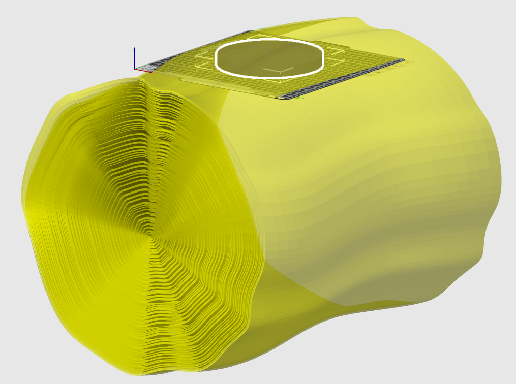
In the slicer software one simply uses the log as a modifier for an object to be printed. When a 3D model is used as a modifier in this way, it means different print settings get applied everywhere the object to be printed and the modifier intersect one another.
In the case of this project, the modifier shifts the angle of the fill pattern wherever the models intersect. A fuzzy skin modifier is used as well, and the result is enough to give a wood grain appearance to the printed object. When printed with a wood filament (which is PLA mixed with wood particles), the result looks especially good.
We’ve seen a few different ways to add textures to 3D prints, including using Blender to modify model surfaces. Textures can enhance the look of a model, and are also a good way to hide layer lines.
In addition to the 3D models, [PandaN] provides a ready-to-go project for Bambu slicer with all the necessary settings already configured, so experimenting can be as simple as swapping the object to be printed with a new 3D model. Want to see that in action? Here’s a separate video demonstrating exactly that step-by-step, embedded below.
from wallabag — all feed https://ift.tt/uncVgRl